Shopping cart

Subtotal $0.00

View cartCheckout

Inside the Ocean

Images and Videos
Collected by ISIIS-DPI

ISIIS-DPI Video Samples
Bellamare
Shape
Plankton Ecosystem

No Plankton No Life

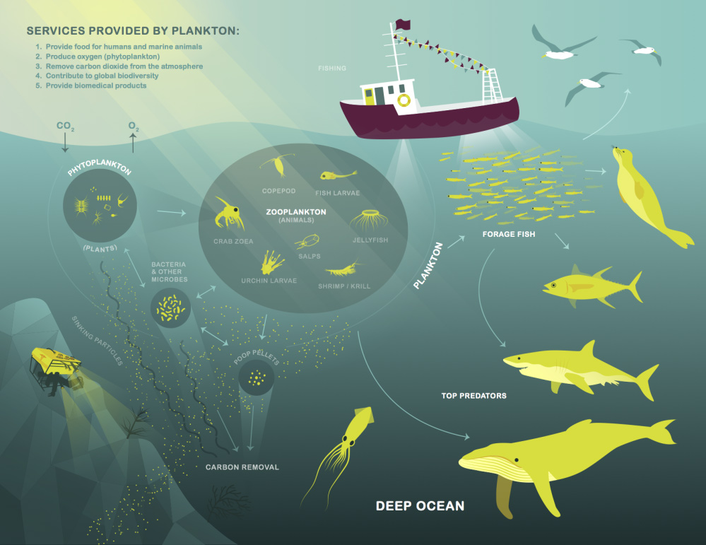
Plankton are a critically important food source. Plankton also play an important role in the global carbon cycle. This cycle captures the Sun’s energy and the atmosphere’s CO2 at the surface of the ocean and releases it to other organisms and other areas of the ocean. Understanding where and when plankton occur at different depths in the ocean allows scientists to get a global understanding of the function and health of the ocean from small to global scales.

Bellamare
Shape
Introducing the ISIIS-DPI

High resolution & high speed

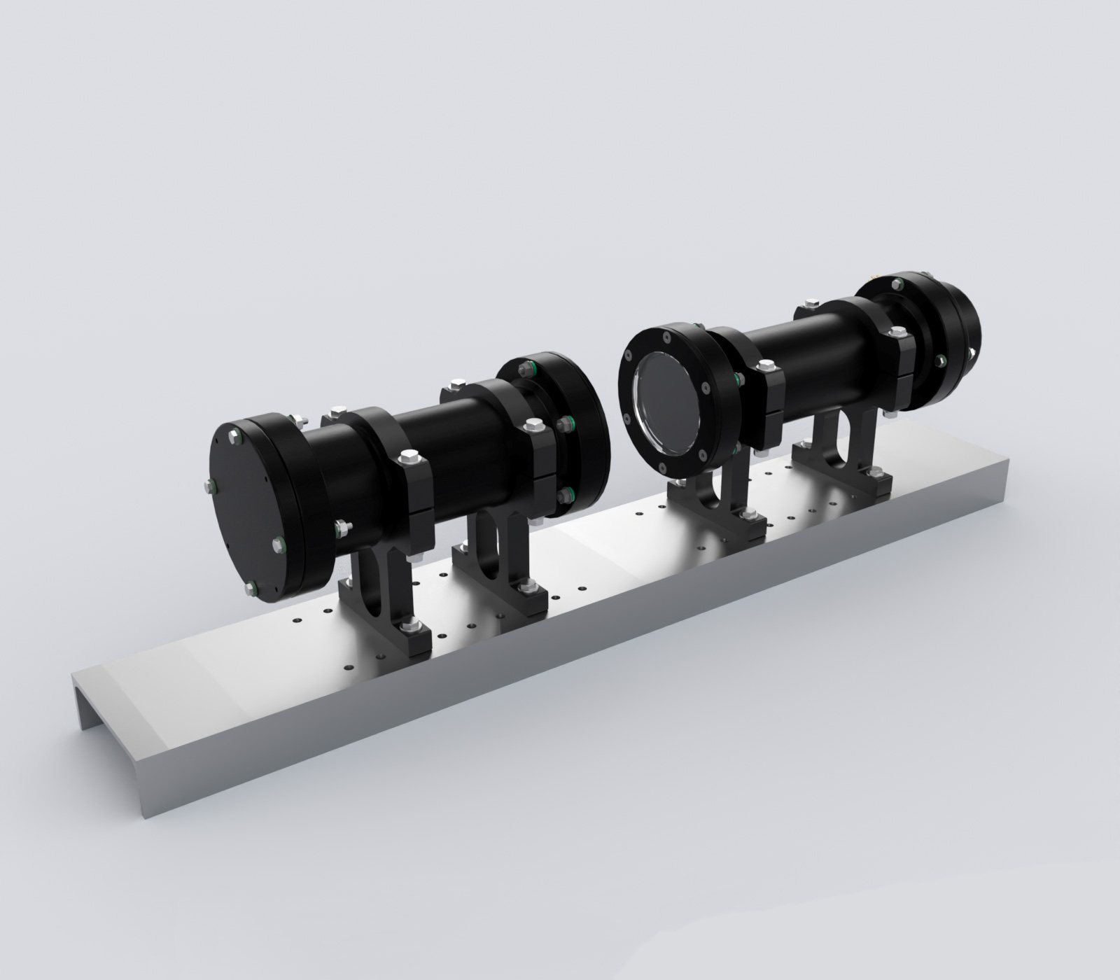
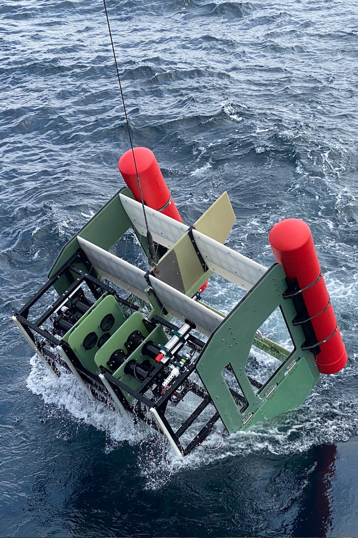
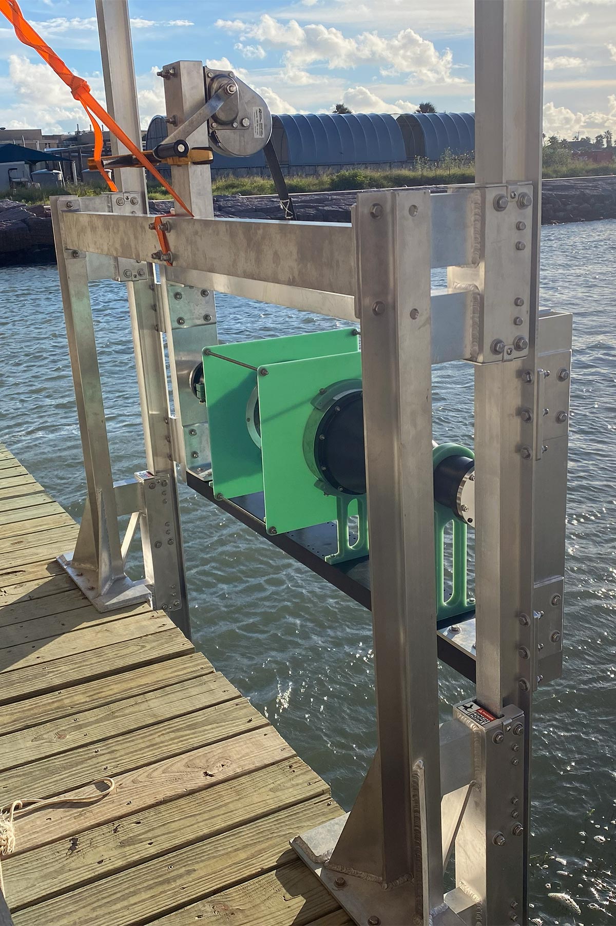
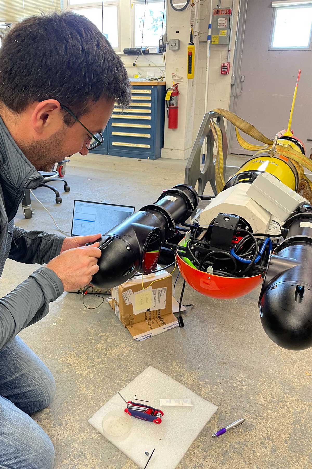
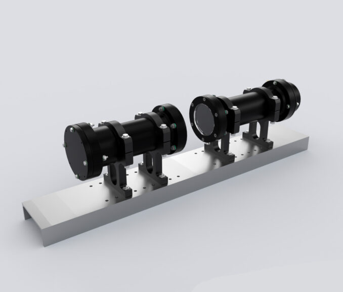
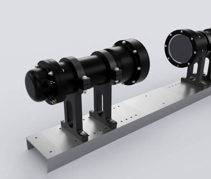
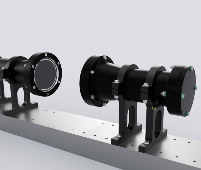
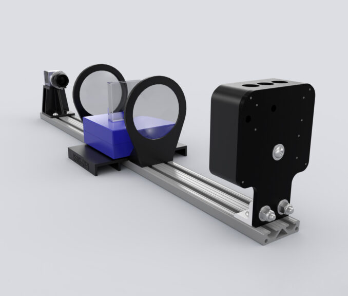
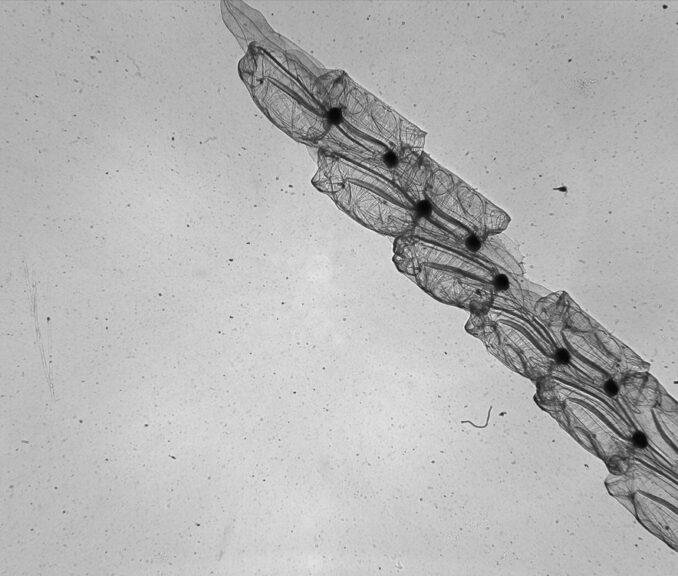
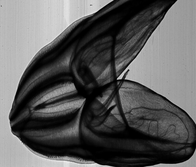
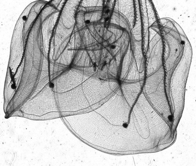
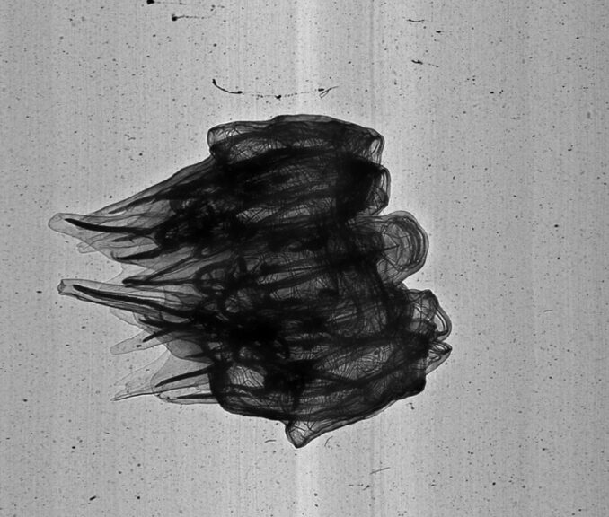
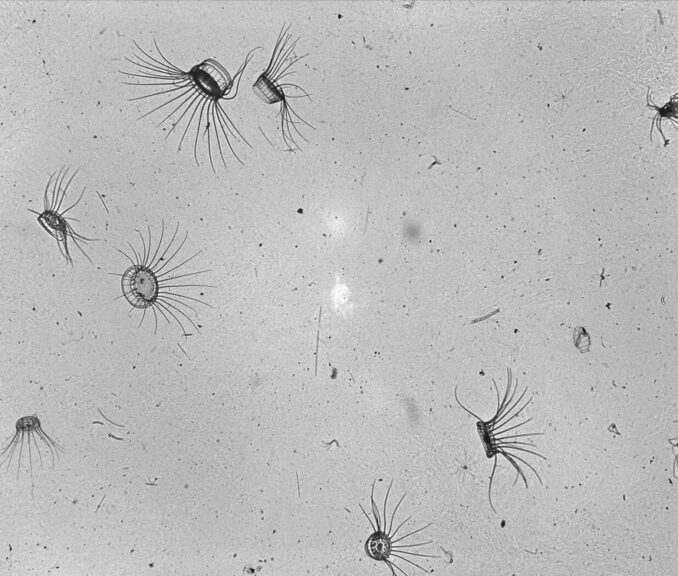
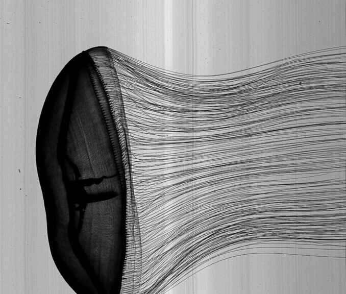
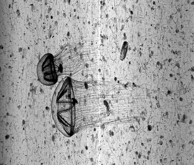
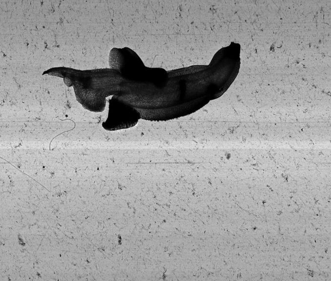
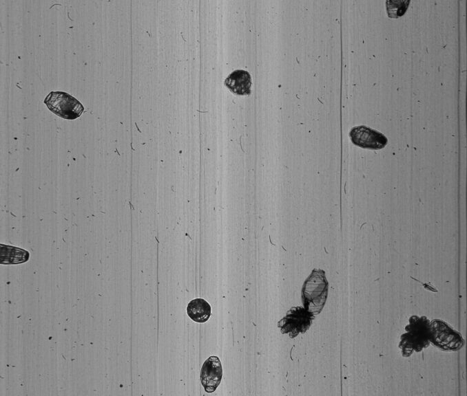
Traditional plankton sampling destroys the very thing it tries to measure.
ISIIS-DPI changes that.


The ISIIS-DPI Plankton Imager is an in situ imaging system designed to observe plankton communities at their natural scale and distribution. It captures high-quality images of plankton, gelatinous organisms, and marine particles in-situ, while sampling large volumes of water at fine spatial and temporal resolution. ISIIS-DPI systems can be configured with line-scan cameras for constant-speed towed surveys, typically around 5 knots. An Area-scan camera configuration provides for more flexible operations such as variable tow speeds, vertical profiling, and stationary deployments. This versatility makes ISIIS-DPI a field-proven platform for studying plankton ecology, trophic interactions, and biological–physical coupling beyond the limits of traditional sampling methods.

Explore the Capabilities

Features of Our Plankton Camera

High Volume Sampling
High volume sampling at high acquisition rates

High Resolution
Clear and detailed image quality

High Water Speed
Capability to operate in fast-moving water 5 knots+

Publications
Extensive research and studies 80+ Publications

Particles Imaging
Plankton, oil droplet & gas bubbles images

Oceanography
Use in oceanographic research

Limnology
Limnology, Mesocosm & freshwater studies

From Lab to Sea

Deployment Methods That Fit Your Workflow

Chosen By

Top Oceanographic Institutions

Quick Comparison

ISIIS-DPI System Configurations

Different research questions require different optical configurations. ISIIS-DPI is therefore designed as a family of imaging systems, allowing researchers to select the configuration that best matches their scientific objectives.

ISIIS-DPI Size Volume Speed Best For
P125 >1mm 4 L 6 kt LTER transects, Ecosystem studies
P100 >500µm 0.74 L 3.25 kt Community-scale surveys
P75 >300µm 0.27 L 3.25 kt Copepods, larvae, gelatinous organisms
T424 Phyto chains 1 ml Slow Diatom chain identification
Benchtop = P75 N/A N/A Lab imaging, ML training
Common Questions

About ISIIS-DPI Systems

ISIIS, short for In-Situ Ichthyoplankton Imaging System, was originally developed in 2005 to image large volumes of water and study ichthyoplankton patchiness in the Gulf Stream off the coast of Florida.

As the system evolved, its defining strength became clear: the ability to image a large depth of field while capturing far more than just plankton. To reflect this broader capability, DPI was added to the name, standing for Deep-focus Particle Imager. Today, ISIIS-DPI is used to image a wide range of particles and organisms across multiple scales.

The ISIIS-DPI Plankton Imager uses Basler machine-vision cameras, selected for their high resolution and global shutter.

  • A line-scan camera is ideal for applications with constant water flow, such as towed vehicle deployments.
  • An area-scan camera provides greater operational flexibility, allowing deployments at variable tow speeds, as well as vertical profiles or stationary configurations such as moorings.

A line-scan camera builds a continuous image as particles pass through the field of view. This approach eliminates concerns about image overlap, sub-sampling, or counting the same organism multiple times.

Additional advantages of line-scan imaging include:

  • Efficient use of the entire viewport diameter, rather than fitting a square image within a circular window
  • True geometric fidelity when the scan rate is matched to water velocity, producing images that are neither stretched nor compressed

An area-scan camera, by contrast, captures discrete frames and may be more flexible in situations where flow speed varies or where imaging at rest is required.

Shadowgraphy does not require very high illumination, allowing operation near the minimum exposure time supported by the camera sensor. As a result, motion blur is generally negligible.
The primary exception is the T424 camera, which may require strobing when used in high-speed towed applications.

Pixel resolution depends on two factors:

  1. The number of pixels on the camera sensor
  2. The physical size of the image projected onto that sensor

For example, a sensor with 2048 × 2440 pixels imaging a 12 cm-high field of view results in: 120,000 µm ÷ 2048 ≈ 58.6 µm per pixel

In practice, an object requires 10–15 pixels across its smallest dimension to be represented adequately. In this example, the system would reliably capture organisms approximately 700 µm to 1 mm in size or larger.

Pixel resolution alone is highly theoretical and does not fully describe imaging performance. This is why ISIIS-DPI systems are specified using size recommendations, which account for resolution degradation across the depth of field.

At the focal plane, pixel resolution correlates closely with measurements obtained using the 1951 USAF resolution test chart. As particles move away from this optimal plane, either toward the camera viewport or the light projector, they gradually lose sharpness.

Most users configure the imager so that resolution degrades by no more than a factor of 2–3 across the usable depth of field. For example:

  • Best focus: 50 µm/pixel
  • Acceptable depth of field limit: 100–150 µm/pixel

This empirical approach is straightforward to document and to test using 1951 USAF resolution test targets, which allows users to report a true resolution over their full depth of field.

To cover a wide range of organism sizes, several strategies are commonly used:

  • Side-by-side imagers: One system optimized for small organisms and shallow depth of field, and another for larger taxa with a broader depth of field. A typical example is pairing a P125 with a T424.
  • Stacked imagers: Multiple high-resolution shadowgraphs stacked vertically to increase the cumulative field of view while maintaining sufficient resolution for identification. This approach has been successfully used for organisms such as megalopae crabs, on cameras installed in estuaries, but it is also standard practice with our towed vehicles.

The imaged volume is calculated as:
Field of View area × Depth of Field × Image rate

Larger ISIIS-DPI systems are capable of imaging up to 80 liters per second per camera, enabling high-throughput, statistically robust sampling.